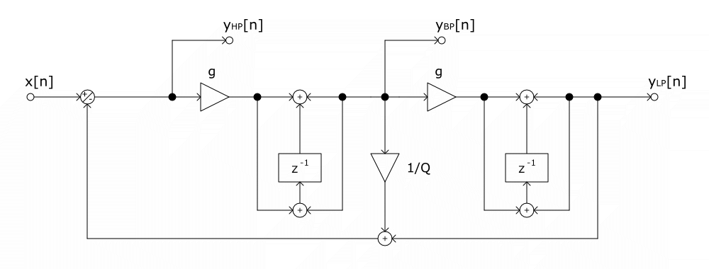
Well, the z-1 are supposed to provide a one sample delay line for getting previously calculated input/output samples as you say. However, on this specific diagram, as you can see the low pass filter signal path always gets a z-1 on its way (close to the bandpass section), which means the LP output will be delayed from the input signal.
Chamberlin’s structure back in 90s if I remember well was one of the first solutions to the audio rate modulation problem of the State Variable Filter digital simulation, but mostly a way to provide with one process call the 3/4 outputs of the SVF. The discretization is done by taking the analog block scheme, replacing the integrators with their discrete versions using Forward Euler and Backward Euler integration methods, which gives the good properties we need for fast modulation and without any z-1 appearing in a feedback loop which could be a problem. The downside is that using the Euler methods gives a bad time-invariant frequency response and even instability for given values of the resonance.
The analog block scheme :

Basically the structure we saw before is obtained by replacing the integrators with Euler Forward / Backward integrators :

The reason why he did that is because the standard method (seen for example in RBJ EQ Cookbook and used in juce::IIRFilter) doesn’t provide all the outputs in one go and the digital structure / topology is not the same. It uses the bilinear transform on the analog transfer function coefficients, which is equivalent to using the trapezoidal integration method on them. It is better in terms of frequency response (a lot !) even if we still have a problem there with the frequency warping of the trap method.
The RBJ EQ Cookbook result is either the DF1 or TDF2 structure below :

The thing we try to do as much as possible thanks to the “topology preserving structures” (either Chamberlin or TPT) is to never have a gain close to the output in the signal path, otherwise at that gain changes, the result might have steps or high amplitude changes in general and so audio artefacts. You can see in Chamberlin’s structure that the “f” is before the integrator so the frequency changes are smoothed. It’s not the case in the TDF2 structure where basically any change in the parameters modify the values of all the b/a gains.
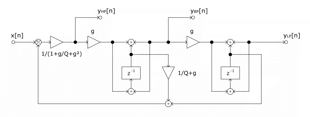
One of the best solutions is to take the analog block scheme like in Chamberlin’s method, but with the integrators discretized by the trapezoidal method instead. It leads to an additional delay-free feedback loop, which can be solved analytically since everything is linear, and we get the dsp::StateVariableFilter method, described in both Vadim Zavalishin’s famous book or in Andrew Simper’s articles. We still have the frequency warping there but that’s another problem…
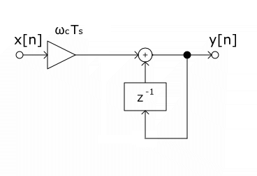
The trapezoidal integrator :

The result for the SVF without the feedback loop solved analytically :
Now with the feedback loop solved (like in dsp::StateVariableFilter) :
Some bibliography :