Linear phase EQ - problem

Linear phase EQ - problem

Hello,
I am not sure if it’s more DSP issue or just programming.

I made some simple plugins. One that generates simple one impulse per buffer, like 1, 0, 0, 0…
And another plugin that calculates FFT for that impulse and draws the freq bin magnitudes and phase shifts.
The aim is to put between those plugins any EQ and make measurements.
And everything works great until I use some linear phase EQ. I tried it with various EQs and get the same results. Here to demonstrate my issue I use Fabfilter Pro-Q2.

But to the point. When I use standard „zero latency” mode I get good results. And it looks like that:

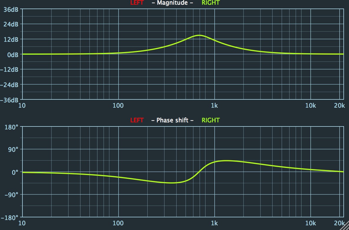
But when I set to „linear phase” or „natural phase” mode I get that shit:

And no matter if I tweak any freq on EQ, even if I flat EQ without any correction, the phase draft is still nasty like that.

I tried to debug it, and found out that when I use „linear phase” (without equing, just flat eq) it moves my impulse from the beginning of buffer (1, 0, 0…) to somewhere in the middle of buffer (0, 0, … 0, 1, 0… 0, 0). I have no idea why it happens. But for buffer size 8192 it moves my impulse exactly 1024 samples forward (like ¼ of buffer size)

What probably should be mentioned: I have constant buffer size for my impulse and for my FFT plugins (8192) and it’s different then my plugin host has set. I am not sure if I have the same issue when all buffer sizes are the same, I need to check it today evening. But even though it doesn’t solve my problem, I don’t want use plugin host’s buffer size cause it’s small and my graph resolution for lower end is not satisfying me.

Could anyone give some hint?

What you are experiencing there is absolutely expectable if you look at it from the DSP theory side :wink:

To clear up your confusion a bit, just put a simple delay plugin (to avoid confusion–> not an “echo” effect but one that just adds additional delay to a track) instead of an eq in your measurement setup and do the same measurement and look at the results that occur if you turn up the delay. You should see a flat frequency response but a phase shift according to the one you see with your linear phase eq.

In theory the phase line should not wrap over from 180° to -180° but continue to bigger positive phase shift values for a simple time shift, resulting in a straight line with constant slope (—> this is why it‘s called linear phase). This can be explained easily by thinking of how many cycles of a sine wave at a given frequency you need to shift for a specific time shift. If the frequency is low, it might be only a fraction of a cycle, for high frequencies it might be multiple cycles. However as you can’t find out if a sine wave was shifted multiple cycles you can just measure a shift value between 0° and 360° or -180° and 180°.

Now the last question might be: Why does the linear phase EQ introduce such a time shift? The answer is that a linear phase can only be obtained by the cost of a bigger latency. This is one of the main reasons why linear phase EQs are not the optimal choice for every application. The Impulse response you measure with a max shifted somewhere to the middle is typical for this kind of filter.

So, TL;DR: Your measurement is fine. If you want to dig deeper take a read on linear phase filter theory :wink:

4 Likes

Hey, great answer and great thanks for it.
So now it’s clear for my. My problem is because „linear phase” EQ generate latency.
So now the question is:
Is there any reasonable way to make my plugin automaticaly recognize there is latency between my impulse plugin and FFT plugin? And ofcourse measure how big that latency is?

I guess what you really would like to display is not phase, but group delay, which is delay per frequency and would display as a horizontal line for a linear phase EQ. Check wikipedia for the math.

1 Like

Latency for an uneven length linear phase filter is (N - 1) / 2, where N is the number of “taps” (or length) of the IR.

You could simply search the buffer for the peak, and assume that‘s your filtered impulse. Depending on the filter, the peak will become less distinct, however it‘ll be still detectable.

Hmm… that’s interesting.
It seems like ‘getMagnitude()’ whould be the best solution, but how to get index of buffer sample with the biggest value?

Write your own function that returns that information…

1 Like

Best solution is iterating over the whole buffer.
Pseudocode:

float absMax = 0.0;
int maxIdx = -1;
for samples:
    if abs(currentSample) > absMax
        {
            absMax = abs(currentSample);
            maxIdx = currentSampleIndex;
        }
        
1 Like

I do not understand these suggestions for finding a max value…

Maybe the OP can explain his question(s) better?

Is it about determining the latency introduced by a linear phase EQ?
If so, the answer is half the length of the EQ IR.

Why search for a peak? And where? In the EQ’s IR?

It’s difficult to say for sure, but based on the poster’s posts in another thread, he is trying to measure the latency caused by other plugins inserted before his own plugin.

2 Likes

I guess he just wants to measure different EQs.

@pajczur:
So the better way to measure this “latency”, would be calculating the group delay, as the phase has already been analyzed by your plugin. This makes more sense than a peak-search when it comes to EQs.